Installation Tips
If you choose to install an ECOsmarte system yourself rather than to hire a plumber, here are some suggestions for you to assemble everything correctly.
- Tools and Parts: suggested shopping list
- Dimensions
- Set-up
- Plumbing
- Wiring
- Back-washing
SHOPPING LIST
(Suggested Parts for Pex-a Installation)
This parts list is the minimum required for an installation. Some situations might require more elbows, pipe, clamps, or other parts. Plan on spending around $900 on materials for installation using Pex-a and 1″ PVC.
Pipe
- (60′) 1″ Pex-a pipe ($2/ft)
- (10′) 1″ PVC Schedule-40 pipe ($12)
- (30′) 1/2″ ID, 3/4″ OD plastic tubing ($2.00/ft.)
PVC Parts
- (4) PVC 2″ male glue to 1″ female thread ($5.00/each)
- (2) PVC 1-1/4″ female glue to 1″ female glue ($2.00/each)
- (1) PVC 1″ elbow ($1.80)
- (1) PVC 1″ ball valve ($10)
- (2) PVC 1″ union ($6.50)
- (3) PVC 1″ female glue to 1″ male thread ($1.50/each)
- (1) PVC 1″ female glue to 3/4″ male thread ($1.50)
- (1) PVC 1-1/4″ male thread to 1″ female glue
Pex-a Parts
- (4) bags of 1″ expansion sleeves ($18/bag)
- (20) poly 1″ Pex elbows ($6/each)
- (4) poly 1″ Pex tees ($6.50/each)
- (10) brass 1″ male thread to Pex ($11.00/each)
- (2) brass 1″ female thread to Pex ($15.00/each)
- (2) brass 1″ Pex to 3/4″ male thread ($9.00/each)
- (3) brass 3/4″ female hose bibs with metal ball valves ($16/each)
- (5-8) brass 1″ ball valves ($25/each)
Miscellany
- vacuum breaker (or a sprinkler solenoid to blow off retention tank)
- (4) two-foot lengths of 2″x4″ wood ($10)
- 30′-50′ flexible drain tubing, 1/2″ ID, 3/4″ OD ($2.00/foot)
- (12) 1″ metal horseshoe clamps
- (8) 3/4″ metal horseshoe clamps
- (4) 1/2″ hose clamps for tubing ($2.75/each)
- (1) box of 1-1/4″ screws
- (1) box of 3″ screws
- (1) can of PVC purple primer
- (1) can of PVC cement
Optional: - (2) 1/2″ barb to male thread ($0.50/each) for tubing from backwash drain
- (2) 1/2″ (or 3/4″) check valves ($40.00/each) for combining drain tubes from backwash
- (1) PVC 3/4″ or 1″ “Y” tee
DIMENSIONS & SPACE
A quick way to assess if the system will fit in your space is to stand with your arms out for the width, put your arm in front of you to the wall for the depth, and hold your arm in the air for the height.
Another way is to allow at least 6′ of wall space for your system, about two feet out from the wall, and at least 6′ vertically.
If arsenic is prevalent, leave room for a fourth tank, or if the hardness level is abnormally high, allow room for a water softener tank and a brine tank. This could make the necessary wall space 8′-9′ long, or else add an extra three feet in front of the system.
If space is an issue, an ECOsmarte system could be crammed together in 4′ of wall space along with ample head room for a tall person to stand, but this would be tight. One tank is 15″ in diameter and the other two or three tanks are 10″ in diameter. The tanks could be clustered together, and the electrode assembly could be mounted on another wall. The electrode assembly is about 20″-24″ wide and roughly 3′-4′ vertically.
SET-UP
1. Positioning the Electrode Chamber and By-Pass Assembly
Select a place on the wall that will be easily accessible and at a convenient height for routine maintenance.
2. Positioning the Tanks
Clean the space, remove the tanks from the boxes, and move them around until you are happy with where they might sit.
Number the tanks.
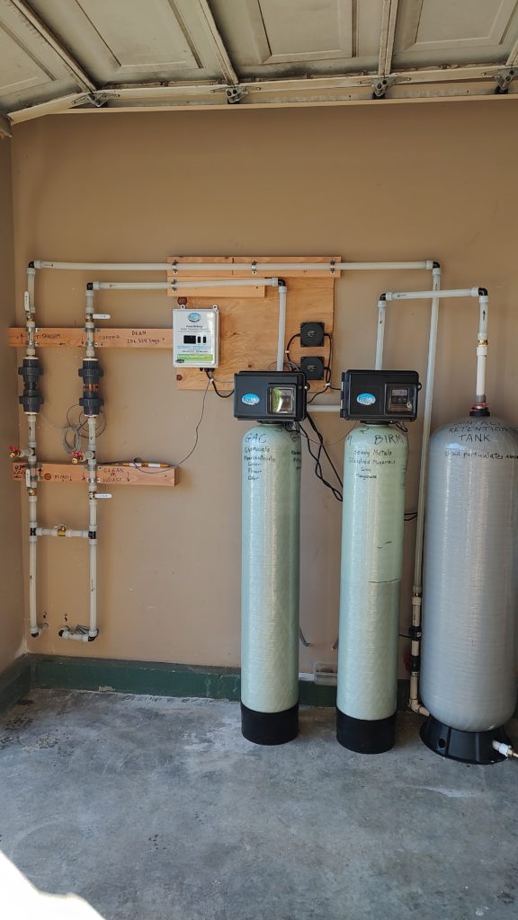
- The large tank is #1. Label it “Retention Tank” or “Contact Tank.”
- Select one of the small tanks and label it #2, and write “”BIRM” or “HYDROXITE.” Depending on your water test results, you may receive one of several different types of media.
- Label the remaining tank #3 and write “GAC,” which stands for “Granular Activated Carbon.”
For the two smaller tanks, allow room behind them for the pipes to be able to come out of the valve: allow at least a foot from the wall. Set them apart sideways to allow enough room for the door of the timer valve to swing open enough to access the control buttons: allow at least a foot and a half between them.
The large retention tank needs room for the ingoing pipe to enter from the bottom on one side, and for the drain to exit on the other. Allow room to make it easy to connect a hose to the drain bib.
Decide where the drains will run. Does the location of the tanks determine how the drain plumbing will run? Will the drain tubes or pipes go through the floor or the wall? Where will the effluent be deposited? Will they be separate tubes or joined into one larger drain pipe?
Plan where several things will be mounted on the wall: the white control box, the transformers for the backwash valves, and the two electrode chambers.
3. Preparing the Tanks
Over time, the media in the filter tanks will foul, break down and become ineffective, and must be replaced. The Birm media in the second tank will last 3-5 years. The Granular Activated Carbon in the third tank will last 8-10 years. Re-bedding a filter tank can take about and hour, and should be done by a professional. If you are inclined to do this yourself, here is the procedure.
- Tape the end of each riser so nothing can enter it. Duct tape is thick is not easily punctured, unlike masking tape. Fold the ends of the tape onto themselves as tabs so they will be easy to grip and remove once each tank is filled. I make two layers of tape, crisscrossed, to make sure that no particles enter inside the riser tube.
- Center the taped basket and riser in the tank. Look inside the tank and note the dimple in the center of the bottom. Holding the top of the riser, make sure that the tip of the basket at the bottom end of the tube seats in that center dimple.
- Put on a dust mask, because the filling process is dustier than you might think. Place a funnel on top of the tank. Open the bag of gravel and pour it into a 5-gallon bucket. It is much easier to handle a bucket than a wiggly bag of gravel. With one finger, hold the top of the riser in the center of the funnel, and slowly pour the gravel into the tank.
- Open the bag of media that was supplied and pour a portion of the bag into the 5-gallon bucket. Add the media. Re-fill the bucket and proceed to pour the media through the funnel until the bag is empty.
- Blow or rinse off the mouth of the tank to clean the threads, and remove the tape from the riser.
- Unwrap the backwash valves and find the valve with three wires coming out the back. The other valve will have only the power wire. Carefully thread the valve with the extra wires onto Tank #2. It is important not to cross-thread this connection, so make sure the threads are started correctly. I lubricate the top of the riser before screwing on the valve. Lift the power cord over the valve and freely spin it into the threads. When it stops spinning. Turn it tight by hand. Ask someone to hold the tank while you turn the valve an extra quarter to half-turn or until snug.
- Place the tank in the approximate position where it might rest after it has been plumbed.
- Do the same procedure with Tank #3.
3. Organizing Tools and Parts
- Be organized.
- Lay out plumbing parts by category.
- Lay out your tools so they are visible, accessible, and in a logical order.
- Keep track of where you put things. Keep instructions handy.
- Sweep, clean up messes, and make a space for recyclables and garbage.
PLUMBING
Plan Ahead
- Take a close look at the installations pictured in the ECOsmarte photo gallery.
- Before starting, make sure you have everything you need to prevent extra runs to the store.
- Call for real-time consultation: (206) 324-5055.
Let me know in advance when you will be installing your system so I can reserve the time to assist you by phone.
Proper Order
Understand the logic behind the proper order of installation. Plumbing the electrode chambers vertically side-by-side makes it easy to add the by-pass directly below them, so that the customer has quick access to all five valves. The drain hose bibs directly below the electrode chambers enable the customer to test raw untreated water and clean filtered water side-by side.
- Install a vacuum breaker somewhere between the pressure tank and the retention tank.
- From the pressure tank, the water enters the titanium chamber from below so that raw water can be tested from the initial hose bib before entering the system.
- After the titanium electrode chamber, which oxidizes dissolved minerals into larger particles, the water flows into the retention tank where the particles can settle to the bottom.
- From the retention tank, the water goes to the birm media tank that removes the finer particles, flocculated minerals, and heavy metals.
- Next the water flows into the third tank containing granular activated carbon to remove chemicals, pharmaceuticals, color, flavor, and odor.
- Now that everything is filtered, it flows from the GAC tank down from the top into the copper electrode chamber that kills bacteria residually through all the following pipes.
- Beneath the copper chamber is a hose bib located so that clean filtered water can be sampled.
- Beneath the two chambers is the by-pass for convenience and swift accessibility.
- Finally, the clean water flows either to the house, or to the next tanks, such as an arsenic tank, a water softener, or a big blue filter.
- Assemble PVC-Pex Connections
Before adding teflon tape, dry-fit metal-plastic parts by hand-threading them; this cuts the threads in the proper position to reduce the possibility of cross-threading. Wrap 6-9 windings of teflon tape around male parts. Plastic-to-metal parts might need 8-9 windings, whereas metal-to-metal hold well with fewer windings. By hand, carefully thread male to female, making sure the two parts are aligned straight and not cross-threaded — especially male PVC into female brass. Using large channel-lock pliers, pipe wrenches, or a vice and wrench, tighten the parts firmly to the point of resistance. - Glue PVC Parts together. Plan ahead: cut lengths 7″ or longer, in case you make a mistake, you change your mind on positioning, or you need to add a part later. The PVC parts apply to all three orifices of the tall retention tank, and the four ends of the electrode chambers.
- Assemble the Retention Tank
If you have a tall retention tank, tip it on its side to access the bottom. Pre-assemble each section before gluing to the tank bottom.
– For the outgoing port, glue the 1-1/4″ to 1″ adapter to a length of 1″ PVC. On the other end of this pipe section, glue a 1″-3/4″ threaded adaptor. Put Teflon tape on the threaded part, and screw on a female 3/4″ hose bib with a metal ball valve. If you are happy with this section, glue it into the outgoing port on the bottom of the tank.
– For the in-going port at the tank bottom, glue a 1-1/4″ to 1″ glue adaptor to a length of 1″ pipe. Glue the other end to an elbow. Above the elbow, glue another short section of pipe and add a ball valve, some pipe, a union, some pipe, and finally a 1″ glue to 1″ male thread adapter. Put teflon tape on the male threads and screw on a brass female thread to 1″ pex adapter.
– For the tank top, depending on the model, either (a) glue a section of 1″ PVC pipe into the provided gray fitting, or (b) glue a short section of 1″ pipe into the female side of the adapter with 1-1/4″ male thread, and the other end of the pipe into a 1″ union, then add another short section of pipe after the union. On the other end of the top of this pipe, glue a 1″ glue to 1″ male threaded adapter. Add teflon tape to the male threads of this 1″ PVC part, and screw on a brass female to 1″ pex adapter. Once the assembly is made, depending on the tank, either (a) pop the fitting into the top of the tank and insert the orange retention clip, or (b) add teflon tape and screw the 1-1/4″ adapter assembly into the top of the tank. - Assemble the electrode chambers. Carefully study photos of actual installations in the ECOsmarte Gallery on this site. Before gluing the 2″ parts into the ends of the electrode chambers, add teflon tape and carefully thread the brass 1″ male to 1″ pex adapters to each of the four 2″-1″ PVC adapters. After checking that nothing is cross-threaded and the connections are tight, glue them to each end of the chambers, holding each chamber upward so that the primer and glue run down away from the chamber rather than inside the chamber.
– Lay out the parts. From top to bottom, the order goes like this for each of the two electrode chambers:
ball valve, pipe, electrode chamber, pipe, tee to drain, pipe, ball valve, pipe, tee to by-pass. With a supply of 1″ collars handy, using the Pex expansion tool, connect all the parts in order.
– Decide on the direction of flow.
Although it doesn’t matter if the electrode chambers are horizontal, vertical, or diagonal, strongly consider plumbing this assembly as described here and as illustrated by the pictures in the gallery. This is the most efficient way to set up your chamber assembly. Water comes from the source, enters the titanium assembly from the bottom, and returns entering the copper assembly from above and flowing to the house from the bottom. The reason for this is that incoming raw water can be sampled before entering the first component, and pure filtered water can be sampled immediately after exiting the copper chambers. Each drain is directly below each chamber, making it easy to shut off and drain the chambers for routine cleaning. By positioning the by-pass directly beneath these assemblies, the customer has the ability to manage all valves for the entire system conveniently at the same location.
– Mount the chamber brackets
– Cut an 8′ 2×4 into four equal lengths.
– Hold one electrode chamber assembly up to the wall at a position that will be comfortable for you to be able to reach and access the highest and lowest valves. Mark the wall at the bottom of the collar on the upper valve. With a level, draw a horizontal line.
– Pre-drill holes through one of the 2×4 sections to line up with the wall studs, and screw it so the top of the board is even with the line drawn on the wall. Screw a second board on top of this first board.
– Bend a 1″ horseshoe clamp around the pipe just under the lower valve collar, and screw the clamp to either the right or left side of the double 2×4’s, so that the entire electrode assembly is hanging by the clamp. Do the same with the other assembly on the other side of the 2×4’s. Allow at least a foot or more between the two hanging assemblies to provide room for a ball valve to be added for the by-pass between the two assemblies.
– Mark a logical area on the wall to fit a 2×4 support between the drain and the valve, or wherever is most logical. Fasten the third 2×4 to the studs, and the fourth 2x4f to the third.
– With a level, position one of the electrode assemblies to be vertical, and proceed to clamp the bottom section to the lower boards.
– With one electrode assembly as a constant, cut a section of pipe to connect the by-pass tee to a valve, positioning the valve handle in the desired direction. Now measure and cut the final piece of by-pass pipe, connect it to the valve and the other tee. With the by-pass set, the lower section of the loose chamber assembly can be clamped to the 2×4.
– Add two additional clamps to each assembly, so there are two at the top and two at the bottom of each assembly. These should now feel secure. - Screw on brass connections.
For convenience, turn the tanks around. Thread and tighten one brass 1″ male/1″ pex to each of the four ports on the back of the two backwash valves. Sometimes it is easier to put one on first so the wrench can rotate a full 360 degrees before adding the second that requires repositioning the wrench. With these fittings on, position the tanks exactly where you want them. Now all tanks should be in place and all fittings should be ready to connect to Pex pipe. - Plumb Pex Pipe.
Using the collars and expansion tool, connect all the pipe. Be methodical. Start from one end and work to the other. The water should travel from the source to the titanium chamber, then to the bottom of the tall retention tank, out the top of the retention tank, to the birm tank, to the GAC tank, to the top of the copper chamber, and finally from the bottom of the copper chamber to the house. (Any irrigation lines should T-off before entering the titanium chamber.) - Drain Tubes
The drain tubes exit the backwash valve from the plastic fitting that is fastened by a plastic horseshoe clip. Slide the tubing onto the fitting and fasten with a hose clamp. Ideally each drain tube should run out to the final drainage site separately. The goal is to have no bends or elbows in this tube that might restrict the flow. If it is necessary to combine both tubes into one larger pipe close to the tanks, install a check valve on each tube so that the water does not flow out of one tank and then backwards up into the other tank. Given some distance, the two tubes could be run into one larger pipe. This backwash water can be directed into a field, the woods, a pond, a downspout, or wherever the roof run-off water flows. It is best not to flood the drain field with backwash water. The end of the drain should never be obstructed or blocked. Although not always practical but for convenience of observation, place the end of the drain pipe in a location where the homeowner can watch what is coming out. - Add Optional 20-Micron Post Filter
This step is not essential, but sometimes helps. If the hardness level is unusually high, fasten a bracket to the wall to support a 20″ housing for a 20-micron pleated filter to remove surplus calcium powder (40 microns). Another alternative for extremely high levels of hardness is to add a water softener.
In areas with arsenic, add the arsenic tank and then the water softener. The option is powder or salt, and my personal choice is powder.
WIRING
- On the wall you will need at least three outlets near enough to the installation so that the wires reach: one for the white control box, and one for each of the backwash valves. In some instances, it is helpful to have at least one extra outlet available for a heater, a light, a radio, or some other accessory. If there is only a single outlet available, buy and plug in a 4- or 6-outlet adapter.
- To connect the wires for the system, follow the instructions in the manual that comes with the unit. Here is a summary.
- Look for two small wires on the back side of the backwash valve on the top of the second tank that contains hydroxite, birm, or the mineral-removing media that came with the system.
- The shortest one has a plastic end with a flat side and a rounded side, sort of like the letter “D.” This clicks down into a hole of the same shape; its purpose is to detect the motion of the impeller that is inserted inside the out-going side of the valve.
- The longer wire that has a white clip on the end snaps into the white clip at the end of the long thin wire from the white control box. It is the only wire that will match this clip, and it clips together only one way.
- The longest thin wire coming out of the white control box has two female connectors on the end: one on a red wire and one on a black wire. This wire extends from the control box to the titanium chamber. Clip the red wire to either tab on one side and the black wire to the tab on the other side, so that one plate will be positive and one plate will be negative. Do not put a black and a red on the same plate.
- The loose coil of thin wire has a red and a black connector at each end. Starting with the titanium chamber, slide the first red connector onto the second tab where the other red wire was just connected. Now there should be two red wires connected to one plate.
- Clip the black wire to the only tab remaining available on the titanium chamber. Now there should be two red wires on one side of the chamber, and two black wires on the other side of the chamber: one plate is positive and one plate is negative. It doesn’t matter which plate is which, as long as the colors match.
- Take the other end of this long coiled wire and connect the red to one side of the copper chamber and the black to the other side, so that one plate is positive and one plate is negative.
- Now plug in the power cords for the controller, and each of the backwash valves. Everything is wi
- After everything is plumbed and the system is running, whenever water is flows the red dot on the white control box should rotate. It will alternate rotating clockwise for about 90 seconds, then counter-clockwise for 90 seconds, back and forth as long as water is running. This alternates the current so that in each chamber the positive plate is active, then the negative plate is active, alternately. This balances the power between the plates.
BACKWASHING
Now that the plumbing is complete and the drains are installed, the tanks must be back-washed to flush out the initial powder before putting the system into service mode.
Open each backwash valve and check the values that were pre-set at the factory. In the beginning, it is best to leave the settings as they came. The only thing to change initially is to set the clock to the current time. Before running water through the system, the tanks must be filled, and the dust from the fresh media must be flushed out. If the dry fresh media has not soaked, it will be so light-weight that it will all blow out the backwash drain. To avoid losing the media you ust put into the tanks, follow these instructions.
- Time:
To set the time, press and hold either arrow button until the letters “TD” (Time of Day) appear. Move the arrow buttons up or down to set the time to the current time. When the time is correct, set it by pushing the left button. - Filling the Tanks
– Close the valve beneath the copper electrodes so that no water goes to the house.
– Open the valves below and above the titanium chamber so that water will begin filling the first tank.
– To release the air in the tank as the water enters, put the second tank into backwash mode and open the by-pass behind the second tank.
– As soon as the first tank is full, the second tank will begin to be filled. Shine a flashlight behind the second tank and watch the water level rise.
– As the water level nears the top of the second tank, close the by-pass valve behind the clock so that no more water enters the second tank. The media must soak for a while before being back-washed.
– To let the air out of the third tank as it fills, push the left button until the digital read-out says “BW” and open the by-pass valve on the third tank. When the water level nears the top, close the by-pass valve so the media can soak. - Running a Manual Backwash:
– Now that the media has had a chance to soak, it is time to backwash the two tanks, one at a time, to flush out any residual powder.
– To run a backwash cycle manually, press and hold the left re-set button until the letters “BW” (Back Wash) appear. Release the button and let the cycle run. The tank will back-wash for ten minutes, and then rinse and re-pack for ten minutes. The display shows the time counting down.
– Start with the second tank. Begin by turning the by-pass lever half-open so as not to blast out all the media. Slowly open valve until it is fully open while watching the color of the water. If it is very dark, close the valve down so that the water becomes grey. After a minute or two, it will be ready to be fully open.
– After the second tank has been through the full 20-minute cycle, do the same with the third tank.
– While each tank is back-washing, go outside and watch how the water is flowing out the end of the drain. Initially the water will be dark and dirty, but as the backwash continues, the color will become lighter. During the rinse the water should be clear.
– During initial set-up, sometimes the backwash will inexplicably stop flowing. Most likely, a clump of media has clogged the orifice by the flow restrictor. To remedy this, close the by-pass valve so no water can enter the tank, pull up and remove the black horseshoe retaining clip, and pop out the restrictor valve. Be prepared for a spurt of water. Look inside and clean out the blockage. When replacing the restrictor, make sure it clicks in, and the horseshoe clip fits snugly. Open the by-pass and continue backwashing.
– Are you satisfied with how and where the water is flowing, or do you want to change it? Now is the time. Let each tank run through a complete back-wash cycle before turning on water to the house.
– With the initial backwashing done, you are ready to run clean filterd water into your house. Open the valves above and below both the titanium and the copper chambers, and close the master by-pass valve. Check that the two switches on the white control box are “on” and
“high,” and that the dots rotate when water is flowing. Turn on each faucet in the house to flush out any old dirt from the pipes, and help yourself to a glass of clear water.
Supply Sources
Media Funnel: isopurewater.com, Item ID U1006 (714-541-6600, CA)
Pliers for Electrode Chamber Unions: FloTool 10627GT GRIPTECH Filter Pliers